Nonsequential ray tracing defines complex objects
Very general objects can be defined and ray traced to optical precision without the need to approximate surfaces using conventional CAD program formats.
Oct 1st, 2003
Very general objects can be defined and ray traced to optical precision without the need to approximate surfaces using conventional CAD program formats. For complete generality covering all major aspects of optical modeling appropriate to nonsequential ray tracing, a method is needed to allow user definition of arbitrary objects with multiple constituent surfaces (see “Designers have several choices,” [below]). Each of these surfaces should support exact ray-surface intersection. The problem consists of several parts. The ray-trace program must first be able to determine whether an arbitrary ray hits any of the surfaces bounding the object. If a ray strikes a surface, then an initial intercept point needs to be determined that is sufficiently accurate for iteration to converge. The surface-defining equations used by the iteration must be user provided. A means for rendering the object is also desired. The object definition can also include other properties, such as material, coatings, polarization, diffraction, gradient index, and bulk- or surface-scattering effects; these topics, however, will not be covered here.
All of these requirements can be met with a two-step approach. First, an approximation of the object is created for fast, approximate ray tracing and determination of which surface the ray strikes. Second, the approximate solution is used as the first guess for iteration to the exact, final intercept point.
For the initial fast, approximate ray-tracing step, a tessellated representation of the object is used. Tesselation involves defining a list of triangles that approximate the actual shape. Tracing rays to triangles is numerically fast and accurate. If the ray does not strike any of the triangles in the list, then the ray is assumed to miss the object. Each triangle can be associated with a particular underlying surface. If the ray strikes a triangle, then the approximate intercept point can be used as the initial guess and the associated surface-iteration function can be used to determine the exact intercept point.
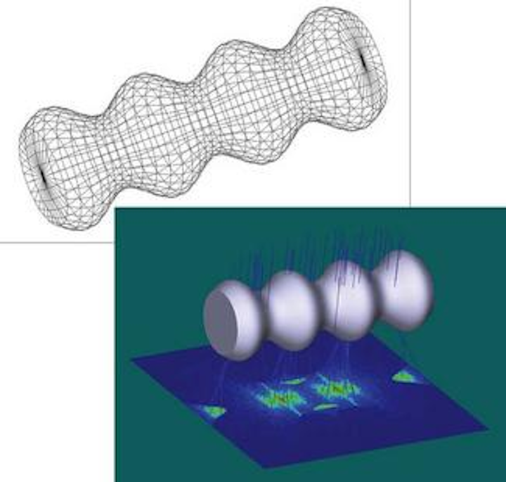
A wire-frame representation generated of the sample object uses approximately 1000 triangles (top). The object is illuminated by a collimated source, forming a pattern on the surface below (bottom).Click here to enlarge image |
One potential problem with tesselation is that some rays can miss all the (flat) triangles, but would have hit the actual (curved) object. Another potential error is that the initial intercept point is not sufficiently accurate for the exact ray-surface iteration to converge. In practice, the former problem is generally more serious as most ray-surface-intercept defining equations converge rapidly with even poor initial solutions.
The solution to the problem of rays erroneously missing the tessellated representation is greatly reduced by increasing the number of triangles in the tessellation, yielding progressively more accurate initial approximations to the object at the expense of slower ray tracing. Note that as long as the rays strike the approximate triangles, and the iteration to the actual surface converges, the final ray-trace results are exact and not dependent upon the accuracy of the object tessellation.
Increasing the number of triangles in the tessellation does not improve the accuracy of the rays traced as long as the rays do not miss the object completely. Another benefit of the tessellated representation is that it serves well to render the object for visualization of the modeled object in the ray-trace program.
Defining the iteration equations
Objects in this method are defined using an external dynamic link library, or DLL. Typically a DLL is written in the widely adopted C or C++ language. The advantage of the DLL is only the code defining the object needs to be supplied by the user to integrate the object into the existing ray-tracing code. The DLL is then called from the ray-tracing program.
To initialize the object, the DLL first defines a list of triangles approximating the solid shape and the association with each triangle to an equation defining the true shape the triangle approximates. The number of triangles used is typically a user-defined parameter. The triangle list can then be used to render the object. Rendering the object allows visual feedback to the user that the object is properly modeled. This portion of the DLL is executed just once for an object.
Most of the nonsequential ray trace is handled by the main program and not by the DLL. To determine whether a ray strikes the user-defined object, the ray is first traced to each of the triangles in the DLL-supplied list. If the ray does not strike any of the triangles, the ray is assumed to miss the object entirely. If the ray strikes one or more of the triangles, the approximate ray-object intersection is passed back to the DLL. The DLL then iterates to the exact solution for the surface represented by that triangle. Iteration is implemented easily using standard methods.1
Using iteration to determine the exact solution for both ray-object intersection and local normal vector orientation is the primary strength of this method. The exact intercept point and normal data are returned to the main program for proper subsequent data processing of the ray.
Example object
Imagine a solid object similar to a cylinder with a radius that varies with the local z coordinate:
x2 + y2 = r2,
where
| Click here to enlarge image |
and
0 ≤ z ≤ zmax.
The end caps needed to form a fully enclosed solid are assumed to be planes, although any other shapes can be defined in the more general case. These defining equations, along with an algorithm to generate the tessellated representation of the object, and the iteration function to compute the exact ray-surface intercept point were incorporated into the DLL.
The defining parameters used in this example are r0 = 2.0, a = 0.5, b = 4.0, p = 0.0, and zmax = 14.0. A Zemax-generated wire-frame rendering of the object uses about 1000 triangles (see figure). A simulated source with collimated rays was added to the model, and the material of the solid was set to be glass with an index of refraction of about 1.52. The rays illuminate the object from above with the resulting illumination pattern and the object rendered at higher resolution.
KENNETH E. MOORE is the president of Zemax Development, 4901 Morena Blvd. Suite 207, San Diego, CA, 92117-7320; e-mail: ken@zemax.com.
REFERENCE
- G. H. Spencer, M.V.R.K. Murty, J. Opt. Soc. Am. 52, 672 (1962).
Designers have several choices
Methods for tracing rays to arbitrary surfaces are widely known and used. These methods generally depend upon a close initial guess for the intercept point and iteration is used to determine the exact point. Care must be taken to determine the initial guess for the ray-surface intercept before resorting to iteration to finalize the exact solution.
Defining geometry
Multiple solid objects are usually defined and placed to build up a complete representation of the optical system. The propagation of light reflecting from and refracting through the objects is then modeled with ray tracing. Typical solid objects consist of several surfaces joined at one or more edges. Each surface can be a different fundamental shape, such as a section of a plane, sphere, or a more general surface defined by a polynomial or other function. Solid objects are usually defined by one of two ways: parametric models or CAD type data formats.
A parametric model creates an exact representation of an object using a number of parameters that define the shape of each of the surfaces that compose the whole object. For example, a conventional lens object might be defined with a spherical front face, a spherical back face, and a cylindrical outer face. The defining parameters for this simple case would be the front radius of curvature, the rear radius of curvature, the center thickness, and a clear aperture diameter.
More complicated parametric models might include edge or chamfer data, aspheric coefficients, or other data. The key property of parametric models is that the ray-tracing program itself maintains exact formulas that define the various surface shapes that bound the solid object. Parametric objects can determine exact ray-object intersections but are limited to the range of object types built into the program.
For ray tracing of object shapes that have no equivalent parametric model supported by the ray-trace program, a common solution is to define the object in a CAD program. Typical CAD programs can create reasonably arbitrary geometry and export the geometry in industry-standard file formats, such as IGES, STEP, SAT, or file formats specific to the particular CAD program being used. The ray-tracing program must then have a capability to import the CAD data file and trace the rays.
The primary limitation of imported objects is the method used to define the object surfaces. Most CAD programs use a NURBS or equivalent spline to define the surface shapes. Splines are piece-wise low-order polynomials that are typically continuous up to the first or second derivative. Splines are generally adequate for mechanical or illumination system design; however imaging systems require an extremely precise definition of the underlying surface, which splines are incapable of supporting.
A telescope mirror, for example, may have aspheric radial polynomial terms of very high order. A lower-order NURBS representation of such a surface may look similar to the desired surface, but when full precision ray tracing is performed significant differences become apparent.